|
Robohatlib 2022282301
Library ro control the Robohat hardware
|
|
Robohatlib 2022282301
Library ro control the Robohat hardware
|
For the software description of the Robohat, see Software description
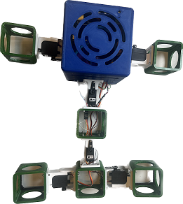
The Robohat is Robot which has a modular design. The basis of the design is the brain. The brain consist of PCBs and batteries.
Attached to the brain are limbs, which are coupled with joints. These joins are driven by servos. By driving those joint, the Robot should be able to walk.
For the processing power, the Robohat uses a Raspberry PI 4
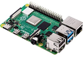
The Raspberry (RPi for short) has multiple connections. Most connection can be used.
Connectors which aren't avaible for users are:
. The I/O-header. The I/O-header isn't accessible, because its connected to the Topboard (see section below) .
. The USB-C power-plug. The USB-C power-plug of the RPi may NOT be used. The power delivery for the RPi is done by the Topboard (see section below). Connecting both the USB-C power-plug and the Topboard can result in weird behaviour of the RPi.
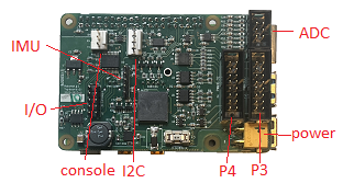
The Topboard is the connection between the Raspberry Pi and the rest of the system.
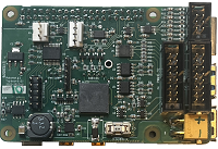
On the Topboard itself, a buzzer, an I/O-expander, ADC, serial console, and an I2C-interface are available.
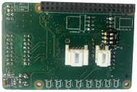
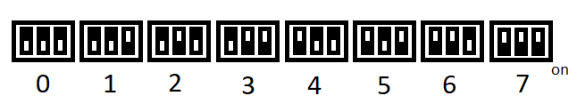
Address of the Topboard
The Topboard has on the backside a dipswitch to sets it address (topboard_switch_value). The default value is 7.
Actually the switch sets the I2C address of the I/O-expander on the Topboard. If for somehow the address of the I/O-expander has a conflict of a other I2C-device (on I2C bus 1) the address can be changed by this switch.
I/O pins
The Topboard has 8 I/O pins, which can be accessed by the I/O header (J2) of the topboard
The maximum input voltage of the I/O (set as input) may not exceed 3.3 V
pinning of the I/O header:
1 + 3V3
2 GPIO 0
3 GPIO 1
4 GPIO 2
5 GPIO 3
6 GPIO 4
7 GPIO 5
8 GPIO 6
9 GPIO 7
10 GND
ADC
3 ADC channels are available on the Topboard, which can be accessed by tge ADC header of the topboard
Do not measure above 3 volts. This could damage the ADC.
pinning of the ADC header:
1 + 3V3
2 ADC Channel 0
3 ADC Channel 1
4 ADC Channel 2
5 scaled battery voltage. DO NOT USE It's actually ADC Channel 3, which is used to monitor the battery capacity.
6 GND
Console
To monitor the RPi a console connection can be used.
The default settings of the console port is: 115200 baud, 8N1
A cable 'TTL-232R-Rpi' can be used (see RS 767-6200)
pinning of the Console connector:
1 GND (black of the 'TTL-232R-Rpi' cable)
2 TXD (data out of the RPi) (yellow of the 'TTL-232R-Rpi' cable)
3 RXD (data in of the RPi) (orange of the 'TTL-232R-Rpi' cable)
Spare I2C
I2C bus 5, is avaible for the user.
pinning of the I2C connector:
1 GND
2 SDA
3 SCL
4 + 3V3
Other connections on the top-side of the Topboard are present, but not user available.
The first one is the power-connector to power the Topboard and the RPi This connector is connected to a power-board. Two other 16 pole headers are avaible (P3 and P4) to connect a Servo-assemblies by flat-cables
The last connection of the top-side of the Topboard is the IMU connector. The IMU located on the top-lid of the housing is connected to this connector by a 5 pole cable.
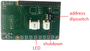
There aren't any user available connections off the back-side of the Topboard
The LED (which goes to the top-lid of the housing) is connected to the 5 pole connector.
The (main) power-board is connected to the 2 pole connector.
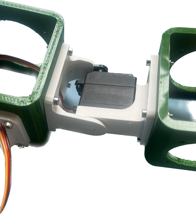
The robohat has limbs to move. These limbs are connected by joints. Those joints are driven by servos.
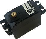
In our prototype we use the DSS-M15 as servo. This servo is modified to have an angle readout.
Other servos can be used. But be sure to use the correct parameters while initializing the Robohatlib.
The servos are driven by 6.8 volts.
The default PWM frequency is 50 Hz
The maximum amount of servos the user can connect to the Robohat hardware is 32 (but can be limited if the servos consumes much power).
These servos will be driven by the Servo-assemblies. For how to connect a servo to the Robohat, see 'Servo-assembly'
A Servo assembly is the connection between the servos and the rest of the Robohat.
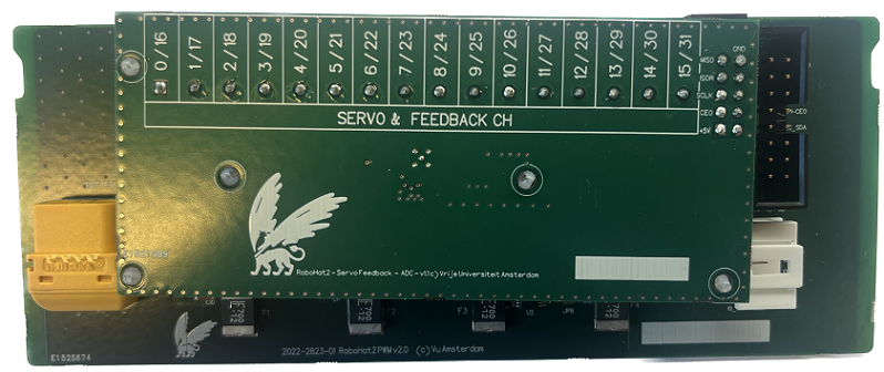
The Robohat can hold 2 Servo assemblies.
A Servo-assembly consists of 2 boards (the PWM-board and the ADC-board) sandwiched together. A Servo-assembly, powers, drives and reads-out the attached servos.
Besides handling all the servo stuff, it has an I/O-expander which the user can use.
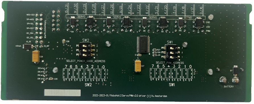
Address of the Assemblyboard
At the back of a Servo-assembly (at the PWM board) are 2 dip-switches present. Onto these switches an address of the Servo-assembly must be selected. To keep it simple, set the address of switch SW1 the same as the switch SW2.
The default value is of assembly-board connected to plug P3 of the Topboard is 0.
The default value is of assembly-board connected to plug P4 of the Topboard is 1.
Note. The 2 dip-switches addressed and position of the flat-cable are used int the Robohatlib::ServoAssemblyConfig
Note. Be sure if you use 2 Servo-assemblies, that the addresses of the assembly boards are different.

Connection of the Assemblyboard
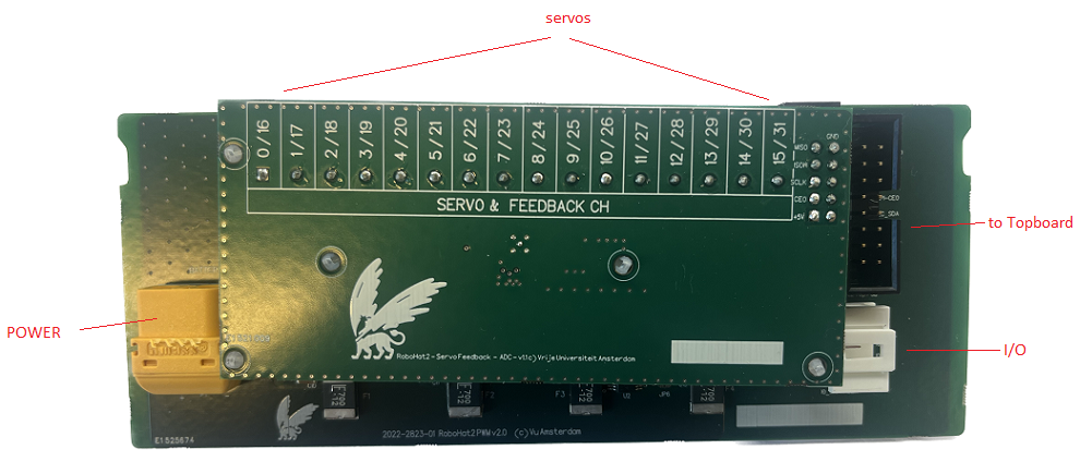
The assembly-board is connected with a flat-cable to the Topboard at connector P3 or P4.
The power is connected to the power connector, which goes from the Powerboard.
I/O connector The assembly-board has also a I/O connector.
I/O connector
1 + 5V
2 IO_4
3 IO_5
4 IO_6
5 GND
Connecting the servos
The Servo assembly handles the power distribution of the servos. Each Servo assembly has to 16 servo channels. Those servo-channels are grouped in 4 groups.
Each group has its own powersupply. The current of each power supply is limited to 5 Ampère.
If the servos in a group take too much power, the groups power-supply will limit the current. This will stall the attached servos of that group, and will result in strange movement of the servos.
Power limitation can be prevented to distribute the servos evenly on all the available servo-channels.
The drawn current of a servo is proportional with its delivered torque. So do not put high torque servos in the same group.
The Servo groups are:
| Servo group | Servos channel | |||
|---|---|---|---|---|
| 1 | 0 | 4 | 8 | 12 |
| 2 | 1 | 5 | 9 | 13 |
| 3 | 2 | 6 | 10 | 14 |
| 4 | 3 | 7 | 11 | 15 |
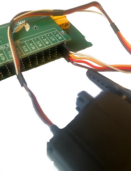
As can be seen on the picture, the BROWN wire of the servo has to be on the side of the PCB with the yellow power connector.
pinning servo
BROWN gnd
RED PWM-signal
ORANGE power
WHITE (but can differ!) pos-measure-signal
The powerboard is the power distributor and the supervisor of the battery.
The battery can deliver a huge amount of power (so be careful, read the Precautions). To keep it save and prevent wrong usage of the battery, each battery has its own powerboard.
If needed, he Robohat has room for 2 batteries. But 1 battery should be enough.
When using 2 batteries, 2 Powerboard are needed.
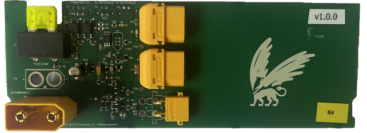
Connections of the front-side of the Powerboard
The Powerboard has no connections available for the user
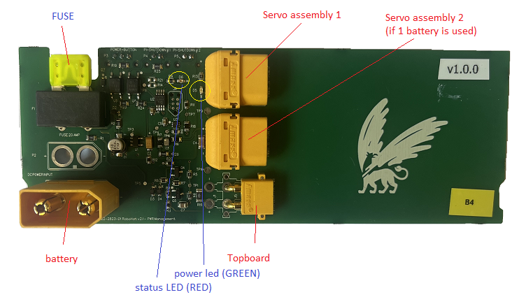
At the top-side there a multiple connectors, which handles the power delivery for the Robohat.
. Battery. At this connector the battery has to be connected.
. Topboard. This connection will power the Topboard.
. Assembly connectors. The 2 other connectors are to power the Servo assemblies.
There are also 2 LEDS present. A red one, for the status, and a green one to see if the power is turned on. (See power-on)
Connections of the backside-side of the Powerboard
At the back-side are the connectors for turning he Robohat on and off.
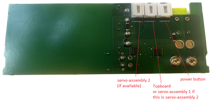
. 3 pole power connector. This has to be connected to the Power-switch-board
. 2 pole (in de the middle) This has to be connected to the Topboard if it is the first assembly-board. When it is the second assembly-board, it has to be connected to the first assembly-board.
. 2 pole servo-assembly. Connect this to the second assembly-board (if available)
Connecting the battery
Always be sure, you connect a battery with enough capacity.
When the battery has enough capacity, the red status-LED will blink two times.
When the capacity of the battery is to low, the red status-LED will flash multiple times.
When the battery is completely dead, nothing will happen.
Turning on the Robohat
User Power on
The Robohat can only be turned on when the accu has enough capacity. To power on, the user has to press the switch of the switch-board.
When the switch is pressed the red status-LED will blink 3 times. When the blinking period ends, the red status-LED will flash multiple times. The user should release the power switch before the flashes stops.
Nothing will happen, when the user releases the button before flashing starts or after flashing is finished. This window of releasing the button is done, to prevent accidentally turning on the Robohat. When the power is on, the green power-LED will be illuminated.
User Powering off
Powering down should be done with the shutdown API-function of the Robohat library.
The user can also shut down the OS (by 'sudo shutdown now' in the console), and turn off the power by pressing switch the same way as turning the Robohat on. (When the switch is pressed the red status-LED will blink 3 times. When the blinking period ends, the red status-LED will flash multiple times. The user should release the power switch before the flashes stops).
Note. Powering down, before shutting down the OS. can result in data loss, or corruption of the SD-card.
Battery low capacity shutdown
The Powerboard will automatically shut down the power, when the battery capacity goes below a threshold (2%). Before shutting down the power, the red status LED will flash for 1 minute. The user can not interrupt this powering-down mode. Although shutting down the power, before shutting down the os, could result in data loss, this hardware feature is implemented to save the battery. The battery can be damaged if used below a capacity of 1%
When using the Robohat lib, the user will get a first warning when the battery capacity goes below 20 %. A second warning will be presented when the capacity of the battery goes down below 10%. When the Robohat lib detects a capacity below 5%, an auto shutdown will be performed to save the accu. This will be a graceful shutdown. The OS will be shut downed before the power is shut downed.
While the accu is in standby, the LED will periodically flash (interval of 6 seconds) to see the battery is still attached to the Robohat.
Its better to unplug the battery and store it in a safe place, when the Robohat os not used.
Fuse
The Powerboard has a fuse. When this fuse is blown, make sure you know the cause, before replacing it. This fuse is rate at 20A, so an accidentally blown of the fuse won't happen. Fuse rating: 20A
The Robohat has also a 'Inertial Measurement Unit' (IMU for short). With the IMU, the Robohat can track its movements.
It can determine its position by reading out the X,Y and Z magnetic fields direction. Also, it can measure the acceleration in the X, Y en Z direction. It has also a build in Gyroscope, so the Robohat can know when it turns.
The IMU is connected to the PI through the Topboard. The IMU is auto-detected, so no addresses has to be set.
Below is a picture how the Robohat PCBs are connected together. The Second assembly is not mandatory. There is no need for the second accu, and the second PWM management board, if the second assembly board is not connected.
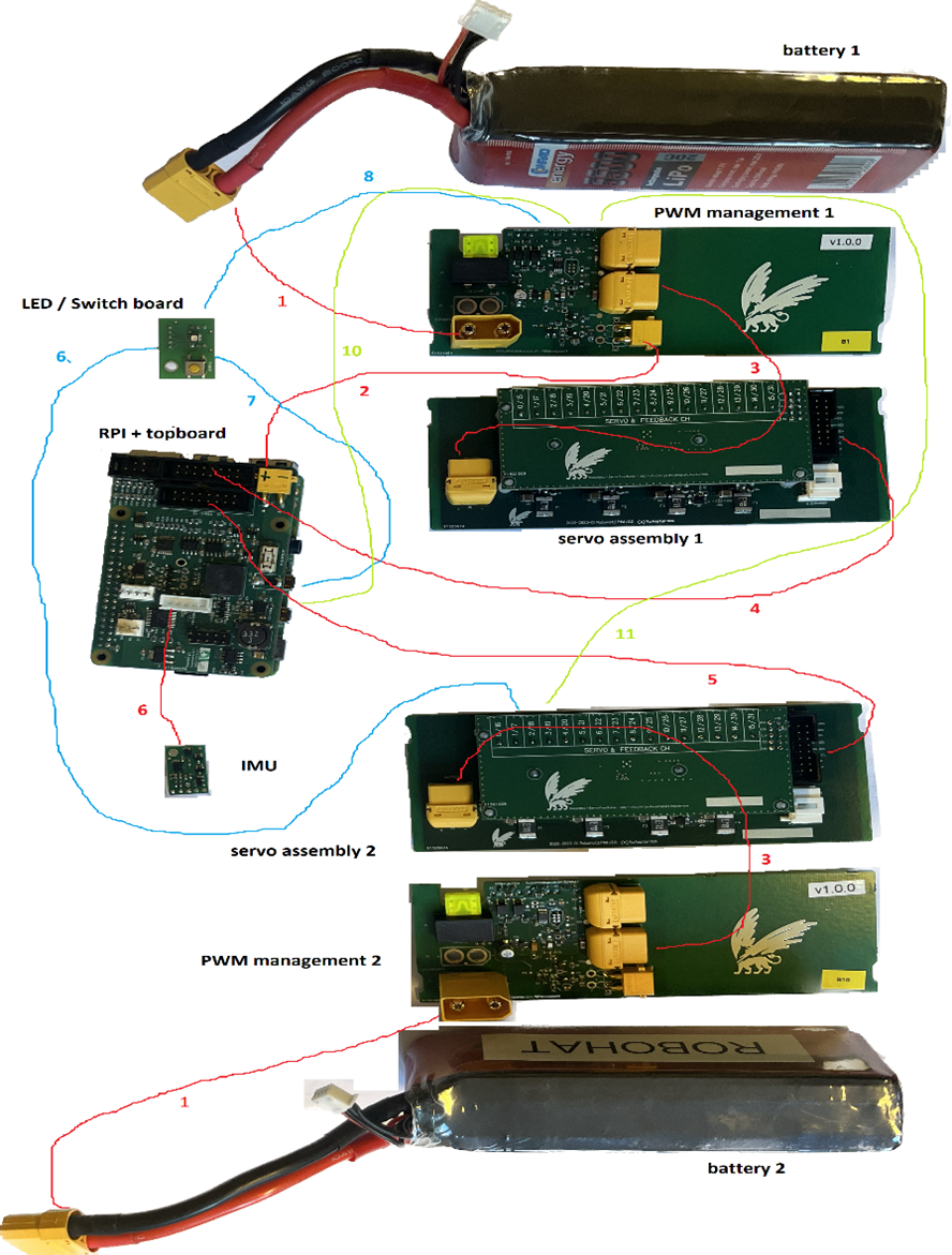
| ID | Connection name | from | from connector | to | to connector | type of cable |
|---|---|---|---|---|---|---|
| 1 | battery connection | battery | - | pwm management board | P1 | cable attached to battery |
| 2 | topboard power connection | pwm management board 1 | J5 | topboard | P5 | 2 wire connection with 2 (small) yellow connectors |
| 3 | servo assembly power connection | pwm management board (1 + 2) | - | servo assembly (1 + 2) | P1 | 2 wire connection with 2 (big) yellow connectors |
| 4 | servo assembly control connection 1 | topboard plug | P3 | servo assembly 1 | P3 | flat cable |
| 5 | servo assembly control connection 2 | topboard plug | P4 | servo assembly 2 | P3 | 16 pole flat cable with 2 black headers |
| 6 | IMU connection | topboard | P1 | IMU | - | 5 pole flat-cable with 2 white plugs ( 30 cm) |
| 7 | LED connection | topboard | RGB-LED | LED / Switch board | P2 | 5 pole flat-cable with 2 white plugs (30 cm) |
| 8 | PWR button connection | LED / Switch board | P1 | pwm management board 1 | P3 | 3 pole flat-cable with 2 white plugs (20 cm) |
| 9 | Pass through PWR connection | LED / Switch board | P3 | pwm management board 2 | POWER-BUTTON | 3 pole flat-cable with 2 white plugs (30 cm) |
| 10 | Shutdown connection | pwm management board 1 | PI SHUTDOWN #1 | topboard | PWR-DOWN | 2 pole flat-cable with 2 white plugs (30 cm) |
| 11 | Pass through shutdown connection | pwm management board 1 | PI SHUTDOWN #2 | pwm management board 2 | PI SHUTDOWN #1 | 2 pole flat-cable with 2 white plugs (30 cm) |