|
Robohatlib 2022282301
Library ro control the Robohat hardware
|
|
Robohatlib 2022282301
Library ro control the Robohat hardware
|
Version: 0.6.0
For the hardware description of the Robohat, see Hardware description
The Robohatlib is a piece of software written in Pyton, to be able to access the hardware. Some PCB-boards of the Robohat hardware, have user selectable addresses. Before using the Robohatlib, the user should know these addresses. For the hardware description see Hardware description
Boards with an address are the Topboard and the Servo-assemblies.
The Startpoint of the RoboHat Library is the Robohat class. After constructing the Robohat class, the 'init ' function (of the Robohat class) has to be executed. The rest of the Robohat class consist of functions which can be used to access the Robohat hardware.
example sourcecode, which moves the angle of the servos
The Robohat constructor, consist out of 3 parameters, 2 ServoAssemblyConfigs (for Servo-assembly board 1 and Servo-assembly board 2) and the switch value of the Topboard.
The parameters consist of 2 ServoAssemblyConfig and 1 switch value
| SERVOASSEMBLY_1_CONFIG | configuration of first servo assembly (ServoAssemblyConfig) |
|---|---|
| SERVOASSEMBLY_2_CONFIG | configuration of second servo assembly (ServoAssemblyConfig) |
| TOPBOARD_ID_SWITCH | Topboard ID switch value (int) |
Parameters of Robohat class
If only 1 Servo assembly is used, the second SERVOASSEMBLY_2_CONFIG parameter can be None but can also be filled with data for a board which can be placed in the future.
A ServoAssemblyConfig is the configuration for a Servo assembly board, which consist out of 4 parameters and is needed by the Robohat constructor.
The parameters consist of a name, 2 switch values and a plug ID
| SERVOASSEMBLY_1_NAME | a name for your own reference |
|---|---|
| SERVOASSEMBLY_1_SW1_PWM_ADDRESS | SW1, switch value of the 'PWM' address (a switch on the assembly board, default 0 or 1) |
| SERVOASSEMBLY_1_SW2_POWER_GOOD_ADDRESS | SW2, switch value if the 'POWER GOOD' address (a switch on the assembly board, default 0 or 1, but the same as SW1) |
| SERVOASSEMBLY_1_PWMPLUG | flat-cable connected to plug P3 or plug P4 of the Topboard |
Parameters of ServoAssemblyConfig
See the Hardware description of the Servo-assembly for SW1_PWM_ADDRESS, SW2_POWER_GOOD_ADDRESS and PWMPLUG
The last parameter of the robohat constructor, is the 'topboard_switch_value' value. The default value is 7.
This value determines the I2C-address of the IO-expander (MCP23008) of the Topboard.
Note. see the Hardware description of the Topboard. for the switch value
Before we have some action, we have to initialize the robohat class. So using this function is mandatory.
This function will give all the attached servos its needed parameters, and it will initialize the rest of the hardware.
The parameters consist of 2 lists of ServoData
| SERVOBOARD_1_DATAS_LIST | List of ServoData for the first group servos 0 - 15 |
|---|---|
| SERVOBOARD_2_DATAS_LIST | List of ServoData for the second group servos 16 - 31 |
Parameters of init function
section of the servoboard config list
| SERVO_NR | servo nr of connected servo |
|---|---|
| MIN_TIME | time of minimal angle of the servo in uS (example: 500 uS) |
| MAX_TIME | time of maximal angle of the servo in uS (example: 2500 uS) |
| OFFSET_TIME | offset time of the servo in uS (example: 0 uS) |
| RUNNING_DEGREE | range of the servo (example: 180) |
| OFFSET_DEGREE | offset of the angle (example: 0) |
| FORMULA_A | first parameter of formula, servo measure-voltage to angle |
| FORMULA_B | second parameter of formula, servo measure-voltage to angle |
Parameters of ServoData
See for the MIN_TIME, MAX_TIME and RUNNING_DEGREE the datasheet of the used servo. In our prototype we use the DSS-M15 as servo.
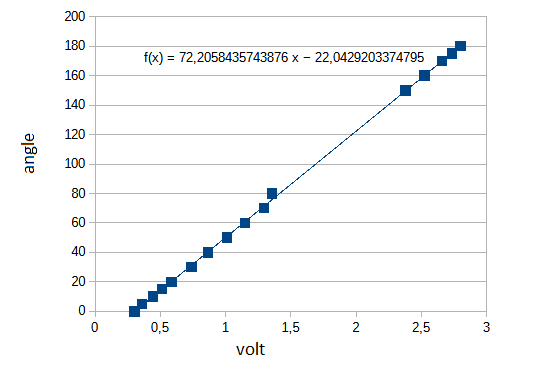
The internal conversion of measured-voltage (out of the servo) to degree, is in the Robohatlib done by a linear formula.
Because each servo has its own linear formula parameters, each servo can be calibrated to get the best readout results.
FORMULA_A is the first parameter of the formula, and FORMULA_B is the second parameter of the formula.
Auto calibration can be down with the api call:
limit_min is the starting angle of the servo and limit_max the angle which the servo stops. Make sure that the given limits are physically possible. The movement of a limb can be out of reach.
This function will set all the servos at a minimum angle, readout the analog values. Next it will set all the servos at a maximum value and reads out the analog values.
With those values read, the Robohatlib will calculate all formula parameters.
The calculated values will be used (until a restart of the Robohatlib) and will be displayed on the console. To make the new parameter values permanent, use the parameter values in the ServoData.
After initialisation of the Robohat class, a device scan will be performed and displayed onto the console. The Robohatlib is now ready to be used.
The maximum servos attached to the Robohat can be 32 or 16, depending on how much assembly boards are present. See Hardware description.
To test if a servo is attached use the function 'get_servo_is_connected '.
multiple servo movement
With the function 'set_servo_multiple_angles ' you set the angle of all the servos. The list has to be a size of 16 or 32 elements. When the size is 16 elements, only the first 16 servos will be addressed. When the list has 32 elements, all the servos will be addressed. If a servo isn't available, the value written to this register is discarded.
Setting multiple servos to an angle
single servo movement when only 1 servo has to be moved, use the function 'set_servo_single_angle '
Setting servo 5 to an angle of 90°
When the servo isn't available, the value written to this register is discarded. To get more accurate reading, the user can calibrate the servos. The auto calibration is described at above, at the robohat.init function section.
To read out a servo angle, use its counter part: get_servo_single_angle '
To check if the servo is at the wanted angle, use get_servo_is_single_servo_wanted_angle '
The user can also use a blocking function: do_wait_until_servo_is_wanted_angle ' to wait until the servo reached the angle.
Update modes There are 2 modes to move the servos. Direct mode, and delayed mode.
The function to user to change the mode is set_servo_direct_mode '
When using the direct mode, the value of the angle is directly set, resulting in a direct movement. Because the movement is instant, (the movement will be fast), the needed force is high. A higher force results in a high current. The powersupply of the Robohat could limit the current, resulting in a strange movement of the servos See Hardware description to distribute the servos in groups to even the current.
Higher forces causes also more stress on the joints of the Robohat.
To limit these problems, the servo steering could be set to delay mode.
Setting the servo steering to delay mode, with an update time of 1mS
The readout which update mode is used get_servo_is_direct_mode '
When to user wants to turn off the Robohat, a proper shutdown has to be performed. Shutting down only the power, could cause corruption of the SD card.
By using the function 'do_system_shutdown ' all hardware will be stopped to an idle state. The OS will be nicely shut-downed closing all its resources, and after a minute the power will go off.
Turning on, must be done by pressing the button as described in /ref hardware
The Robohat library can generate 3 interrupts. The first one is the interrupt of the Topboard IO-expander, the 2 other interrupts can be generated by the Servo-assembly-boards.
When an I/O pin of the Topboard IO expander is set as an intput, it can generate an interrupt. To catch this interrupt, a callback function has to be set with the function 'set_topboard_io_expander_int_callback( the function)' of the Robohat library. This callback function has an integer as parameter. This parameter is set to tell the callback function which IO pin has cause the triggering of the interrupt.
Both assembly board has a IO-expander which is used to detect if the power delivery for the servos is working correctly. To detect a power fail, only 4 IO pins of the expander are used. IO pin 4,5 and 6 can be used by a user. When these pins a configured as an input, in can generate an interrupt. To catch this interrupt, a callback function has to be set (for board 1) with the function 'set_assemblyboard_1_io_expander_int_callback( _the_function)' of the Robohat library. This callback function has an integer as parameter. This parameter is set to tell the callback function which IO pin has cause the triggering of the interrupt.
Use set_assemblyboard_2_io_expander_int_callback, for board 2
At the Topboard of the Robohat, an ADC and some I/O are available for the user. See Hardware description
ADC The ADC has some functions, which will reply in volts measured.
Note. The maximal voltage which the ADC can measure is 3 volts.
For single channel use: 'get_topboard_adc_single_channel ' For all the channels at once use: 'get_topboard_adc_multiple_channels '
I/O
There is also I/O pims avaible. To set the function of a pin, use: 'set_topboard_io_expander_direction '
When the pin is set an output, the output can set by 'set_topboard_io_expander_output '
When set a pin is set as input, the status can be read by 'set_topboard_io_expander_output '
At the pin an interrupt can be used. Do to so, a callback function has to be attached by: 'set_topboard_io_expander_int_callback '
For the connections of the ADC or I/O see Hardware description
An inertial measurement unit is present. This unit can be used to determine the position and direction of the movement of the Robohat.
At this moment only raw values are avaible: 'get_imu_magnetic_fields ' for the detection of movement in X, Y, and Z direction
'get_imu_acceleration ' for the detection of acceleration in X, Y, and Z direction
'get_imu_gyro ' for the detection of rotation in X, Y, and Z direction
When the capacity if battery falls below a threshold, the user will be notified (by an alarm and a message to the console). When the capacity is wat too low, the Robohat will be shutdown (to save the battery).
If the user want to know the battery capacity, the user can use the function: 'get_battery_percentage_capacity '
At the top of the Robohat a LED is mounted. This LED with be illuminating white when the Robohatlib is initialized.
By using the function 'set_led_color ' you can set the LED to WHITE, RED, GREEN, BLUE, YELLOW, and PURPLE. This function will also turn on the LED.
The user can turn off the LED by the function 'turn_led_off '.
If the user to turn on the LED again, the user should use 'turn_led_on '. The color off the LED, will be the color last used.
The user can also use OFF or ON with the function set_led_color. This will turn the LED off or on.
When the user want to know which color the LED currently is, the function 'get_led_color ' should be used
The Robohat is equipped with an buzzer.
There are multiple function the user can use, to create a sound such as: 'do_buzzer_random ' 'do_buzzer_slowwoop ' 'do_buzzer_beep '
The duration of the sound is limited
There is also a function which generates a sound until the sound is stopped
The function: 'do_buzzer_freq ', gives a sound at a given frequency, until it has turned off with 'do_buzzer_release '
There are a lot more functions present in the Robohatlib. Take a look at the Robohat class for the full function list.
The Robohat library comes with 2 test-applications.
Test application
The first one is the 'Test' application. This test application can test all the functions by typing commands at a console.
Test.py ( located at the root of the project )
TestConfig.py ( located in the testlib directory )
These files should be placed in the directory where the 'robohatlib' is placed
To execute the test application:
example to execute the test python module. The commands can be placed in a batch file (see a batch ile called test, in the root directory of the project)
When starting the Test application (which initialises the Robohatlib) a summary of the IO will be printed on the console. The user will be notified when a IO device fails.
By typing help (+ [RETURN] ) a list with commands will be displayed.
By typing a command (+ [RETURN] ), a function of the Robohatlib will be executed.
SerTest application
The second application is 'SerTest'. This test application can test all the I/O by selecting a test item in a menu.
SerTest.py ( located at the root of the project )
TestConfig.py ( located in the testlib directory )
example to execute the test python module. The commands can be placed in a batch file (see a batch ile called test, in the root directory of the project)
When starting the SerTest application (which initialises the Robohatlib) a summary of the IO will be printed on the console. The user will be notified when a IO device fails.
A menu will appear. By section a menu entry (+ [RETURN] ), a function will be executed.
A menu list will be displayed when only [RETURN] is typed.